Boundary Conditions |
To develop a water surface profile (WSP) through the culvert using Gradually Varied Flow calculations one or more boundary condition must be defined. A boundary condition is a section of the channel where the depth of flow is known at a given flow rate. For culverts, these boundary conditions occur at or near the inlet and outlet.
For backwater calculations (WSP calculated from downstream to upstream) a downstream boundary condition is necessary. When performing frontwater calculations WSP calculated going downstream) an upstream boundary condition is required. Determining the type of boundary condition and calculation (backwater verses frontwater) needed is a function of the hydraulic slope and tailwater depth. In FishXing the tailwater depth is defined by one of the available Tailwater Methods.
Boundary Conditions used by FishXing for Gradually Varied Flow Calculations are illustrated below.
Where:
yTW = Tailwater depth, measured from outlet bottom (negative below bottom, positive above bottom)
yc = Critical depth
yn = Normal depth
yfs = Free surface depth, a function of (0.71*Ac)
Ac = Cross sectional area at critical depth
HL = Inlet headloss
GVF = Gradually Varied Flow (arrow shows the direction of calculation)
RVF = Rapidly Varied Flow (arrow shows the direction of calculation)
Inlet Boundary Conditions Used in FishXing
In FishXing, inlet boundary conditions are only required for hydraulically Steep sloping culverts (yc > yn).
Steep Slopes
GVF Boundary Conditions = Critical Depth at inlet.

Frontwater GVF Calculations begin at critical depth at inlet and end at outlet
Outlet Boundary Conditions Used in FishXing
Outlet boundary conditions required on non-Steep slopes or on Steep slopes with tailwater depth > critical depth (yTW > yc ).
Mild, Horizontal, Adverse, Critical Slopes
Type 1: GVF Boundary Condition = Tailwater Depth
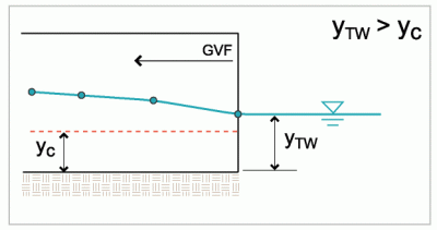
When the Tailwater Depth (yTW) is greater than Critical Depth (yc ) the culvert is controlled by the downstream water surface. Backwater GVF calculations begin at the outlet and proceed upstream to the inlet.
Type 2: GVF Boundary Condition = Critical Depth
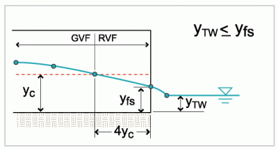
When Tailwater Depth (yTW) is less than the Free Surface Depth (yfs) the flow is passing through Critical Depth (yc ) and entering a zone of Rapidly Varied Flow. RVF is approximated linearly by drawing the flow profile from critical depth at a distance of 4yc from the outlet through yfs at the outlet. When yTW is negative, an outlet plunge exists.
Type 3: GVF Boundary Condition = Critical Depth
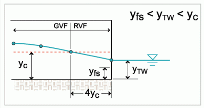
When Tailwater Depth (yTW) is less than the Critical Depth (yc ) and greater than Free Surface Depth (yfs) the flow is passing through critical and entering a zone of Rapidly Varied Flow. The water surface within the RVF zone is approximated by drawing the flow profile from the tailwater elevation at the outlet to critical depth at a distance of 4yc upstream from the outlet.
Steep Slopes
For Steep slope culverts, a downstream boundary condition is only needed if a backwater calculation is required.
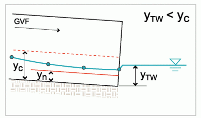
In this case the Tailwater Depth (yTW) is below critical depth, so no backwater calculation is required.
Type 4: Steep Slope with GVF Boundary Condition = Tailwater Depth
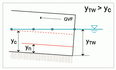
For hydraulically Steep slopes, if the Tailwater Depth (yTW) is greater than the Critical Depth (yc ) then the downstream boundary condition is yTW and a backwater calculation is performed. In addition, for all Steep sloping culverts a frontwater calculation is also performed. Determine the extent the flow profile is influenced by the tailwater depth requires comparing the frontwater and backwater generated profiles and identifying the location of a hydraulic jump, if one exists.
See: Outlet Plunge, Outlet Drop, Tailwater Calculations, Hydraulic Jumps,